Generally, the voltage difference after rectification of the input voltage should be 6~10V higher than the output voltage.
[Calculation formula: input AC*1.414-output DC= 6-10V]
The relationship between the output DC voltage and the secondary AC voltage of the transformer is as follows:
Output: when ±5VDC, the transformer selects 2*9VAC
Output: when ±9VDC, the transformer selects 2*12VAC
Output: when ±12VDC, the transformer selects 2*15VAC
Output: when ±15VDC, the transformer selects 2*18VAC
Output: when ±18VDC, the transformer selects 2*20VAC
Output: when ±24VDC, the transformer selects 2*25VAC
Output: when ±30VDC, the transformer selects 2*30VAC
Output: when ±36VDC, the transformer selects 2*35VAC
About heat dissipation:
The standard heat sinks of the kits and finished boards sold in this shop can withstand close to 0.2 watts of power consumption. It can be estimated according to PT=VI (voltage difference * load current). When the heat is too large, it is recommended to use the chassis bottom plate Perform heat dissipation.
installation tips:
This power supply kit, as long as you carefully follow the markings on the PCB board, carefully solder the parts, and do not solder wrongly, you can ensure that the power is successfully once. According to the experience of other customers, the following points need special attention:
Constant current diode 2ma (202) and 5.6ma (562) are easy to confuse. Please note that the transparent diode of the strip package is 562, and the other two transparent diodes are 202.
The power tube does not need to install mica sheet and insulating ring
The larger the value of the adjustable resistance, the lower the output
Official information:
https://www.amb.org/audio/sigma22/
Size: 110mm*93mm*1.6mm
Upgrade the Zener diode to TL431 (TO-92 package), which is equivalent to 2.5Vdc, but its performance is much better than general Zener diodes in all aspects
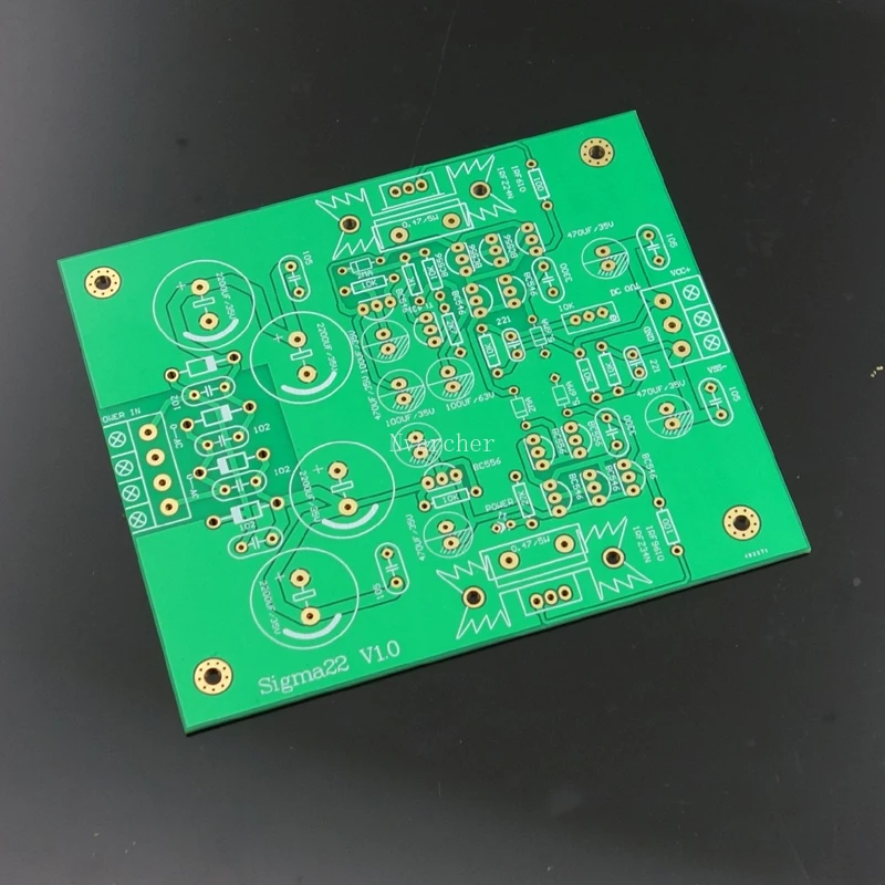
Product description:
This power supply is based on the Sigma22 V2.0 high-performance DC voltage regulator circuit. By replacing the trimming potentiometer, it can be used as a 5V-35V dual power output. It is very suitable for pre-amplifiers, decoders DACs, headphone amplifiers and power amplifier voltage-level regulators, etc. use.
Technical features:
1. Ultra-low noise (μV level), high PSRR
It uses a fully discrete single-stage error amplifier with a gain of 102.5dB, and uses capacitance multipliers to enhance PSRR (power supply rejection ratio). The whole can be divided into three stages, the first stage is differential amplification and current mirror current mirror/constant current source; the second stage is the voltage amplification stage (VAS), and the third stage uses the field tube as the source follower. What is commendable is that the output noise is only about uV level under load This is three levels less than the common mV, which is nearly a thousand times worse. No ic is used, so that the entire design can control each control loop node so that the various performance parameters of the voltage regulator reach the best state of Zui
2. No current limit
Simply put, the field tube MOSFET with high current output has no output current limit, as long as the heat dissipation is sufficient. The bottleneck of output limitation lies in the wattage of the cow, the rectifier diode, and the fuse (but note that the original version did not use a fuse on the board...) and the feature of no current limitation allows the S22 to support many instantaneous large current needs. Especially power amplifiers. As long as you want current, S22 is ready. Remarks: The version currently on sale in our shop is a low-current version. It is affected by rectifier diodes, heat sinks, PCBs, etc. It is recommended that the output voltage does not exceed 30V and the load current does not exceed 1A. The standard heat sinks of the kits and finished boards sold in this shop can withstand close to 0.2 watts of power consumption. It can be estimated according to PT=VI (voltage difference * load current). When the heat is too large, it is recommended to use the chassis bottom plate Perform heat dissipation.
3. Ultra-high bandwidth
The fully discrete design of the S22 allows the bandwidth to be expanded by Zui Jia. Since the output impedance of S22 is even lower than Zui&x27;s expensive low-ESR electrolytic capacitors, the fast charge and discharge speed of S22 is greater than that of traditional large pond capacitors. Surprisingly, the output impedance of the S22 is only μΩ (generally the capacitance is about mΩ, a difference of 1000 times). In fact, the test line occupies more of the impedance during the measurement, so the value is still overestimated. For capacitive loads, even as high as 10000μF, S22 can be calm and comfortable, which makes S22 have more application possibilities. The inflection point frequency of the low-pass filter is as low as 1.6 Hz to prevent diode switching noise from entering the error amplifier behind. In addition, this part has a soft-start function.
4. Flexible output, low internal resistance
The output voltage of S22 is adjustable, which is mainly determined by the ratio of the Zener diode and the two resistors.
Common output voltages are typically ±5V, ±9V, ±10V, ±12V, ±15V, ±18V, ±24V, ±27V, ±30V or ±36V. (even higher)
The output impedance of sigma22 is much lower than that of Zui&x27;s good low-ESR large-capacity electrolytic capacitors on the market. Due to the high bandwidth design of sigma22, sigma22 can easily cope with the ever-changing amplifier current demand, ensuring that the back-end amplifier can realize Zui&x27;s great potential . (The output impedance is as low as μΩ, 1Ω=1000mΩ=1000000μΩ)
5. Automatic tracking of positive and negative voltages
There is tracking between the positive and negative output systems, that is, the negative output will follow the positive voltage at any time, which makes the voltage symmetrical, also greatly increases the common mode noise rejection ratio (CMRR), and avoids the popping sound of the switch. The positive and negative voltage error is less than 3%. If you need more precise consistency of the positive and negative voltage, you can fine-tune the resistance of the resistor R11=10K.