One、An overview,
The single/double/four-way WIFI relay module uses ESP-01 as the WIFI module, and with the mature and stable 8-bit MCU chip of ST Company, it only needs a simple configuration process to realize the wireless control of the 2-way relay using mobile APP in the local area network
Second, functional characteristics
1, On-board high-performance microprocessor STM8S103 and ESP-01 WiFi module;
2. The module has two working modes:
Mode 1: the phone is directly mounted on the WiFi module;
Mode 2: Mobile phone and WiFi module are simultaneously mounted on the router;
Additional Features: It can also be used as a USB relay when the ESP-01 is unplugged.
3. Transmission distance:
(1) In the open environment, the maximum stable transmission distance is 100m when the mobile phone is mounted on the WiFi module;
(2) When WiFi module and mobile phone are carried on the router at the same time, the transmission distance depends on the signal of the router
The weak.
4, Use SmartConfig technology to complete the ESP-01 WiFi module account and password configuration on the mobile APP, the configured account and password has power memory function;
5, Onboard 12V,10A/250V AC 10A/30V DC relay, can continuously pull up to 100,000 times, with diode drain protection, short response time;
6, On-board mode selection and real-time working status indicator;
7, reserved UART debug interface and STM8 SWIM program download interface.
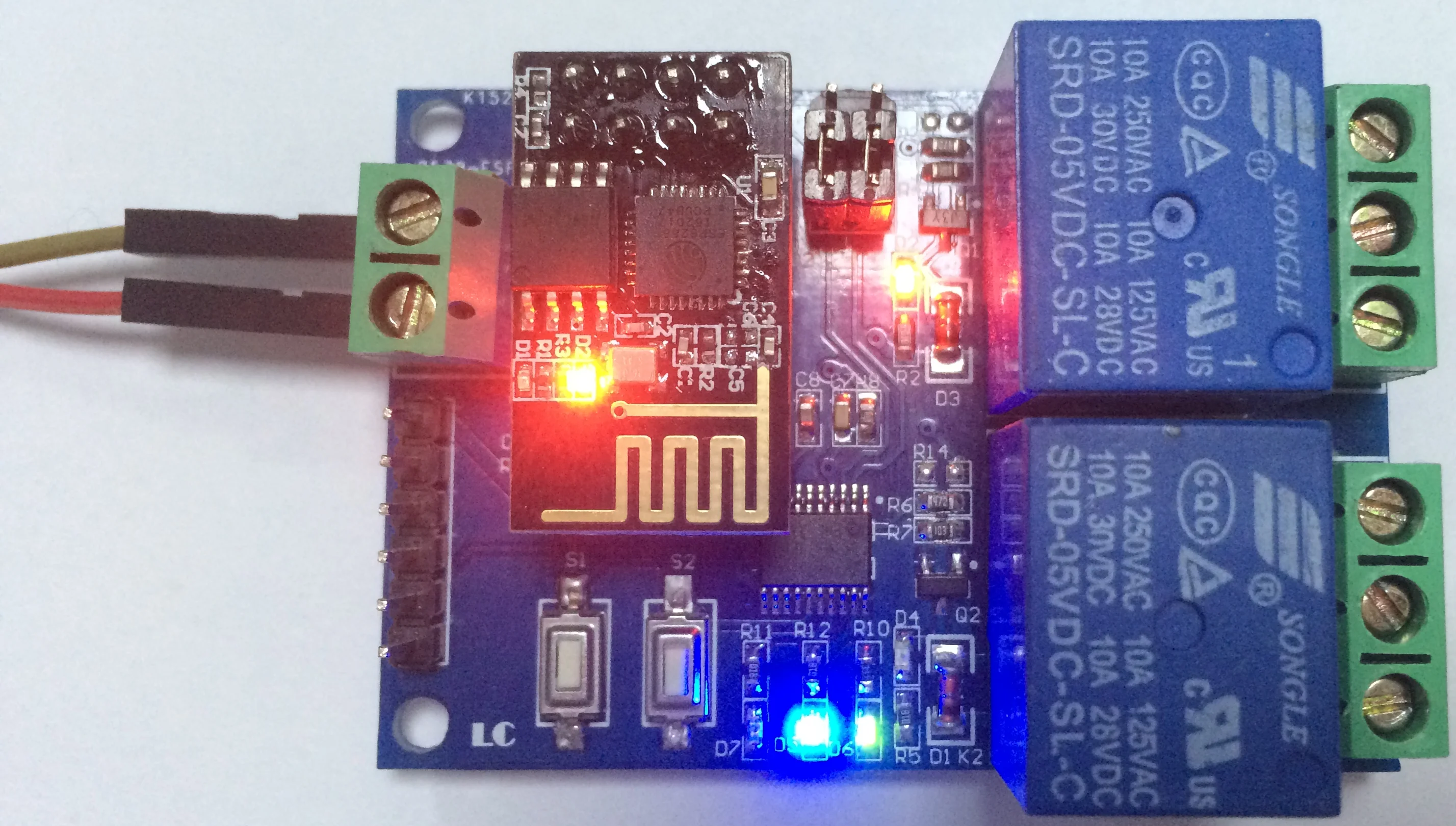
III. Hardware introduction and description
Board size Single way:57.4*29mm Two way:59*40mm Four ways:60*63mm
Board function description:
1. Introduction of onboard resources:
In +, In - : 12V power input;
Tx, Rx: UART serial port pin;
12V, GND, SWIM, NRST: STM8S microcontroller program download port.
Press S1: Mode switch. The default is Mode 1
Button S2: Restore factory Settings
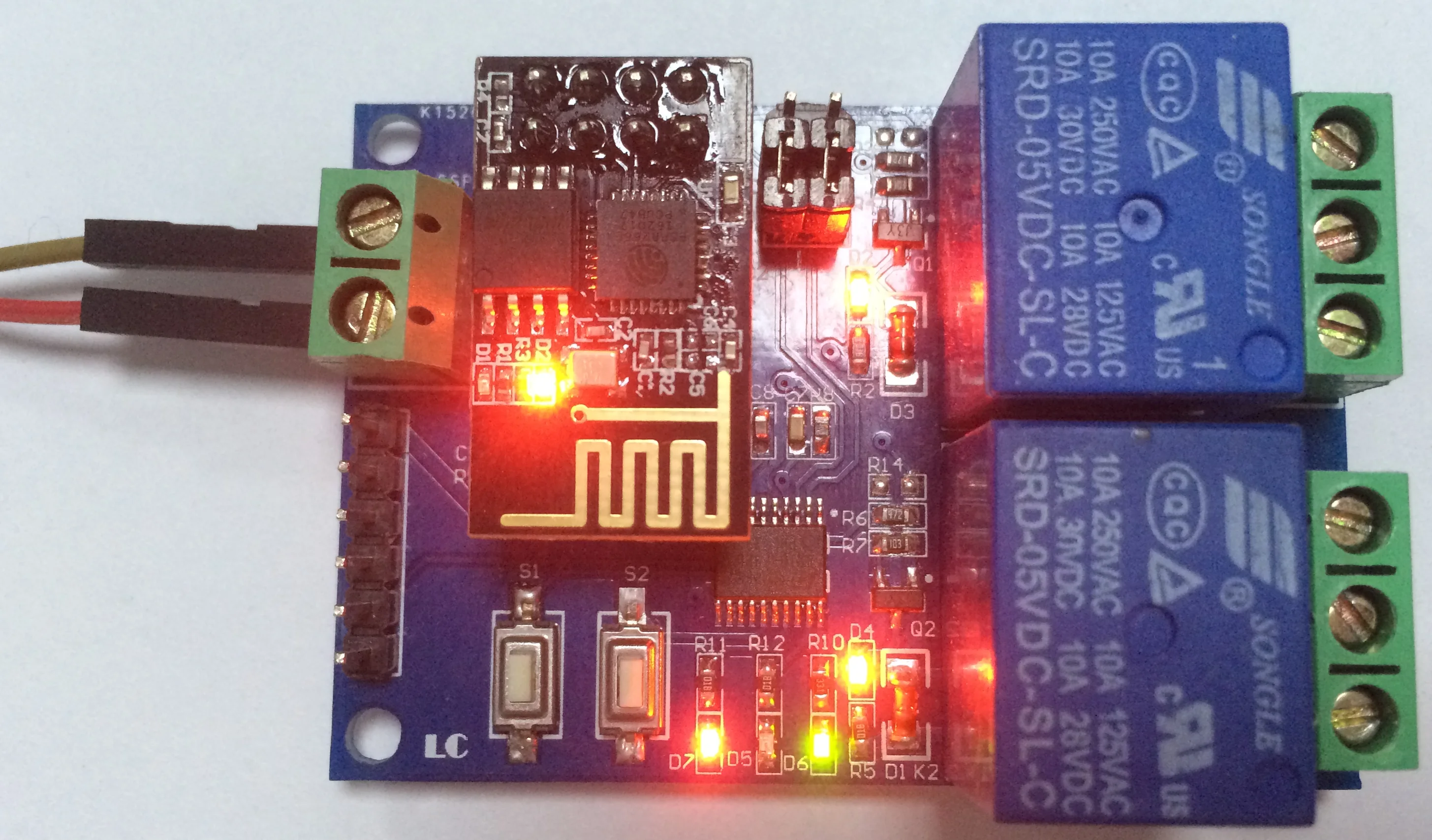
LED D2 and D4 (red) : Relay working indicator light, on when turned on
LED D7 (red light) : Mode 1 indicator light
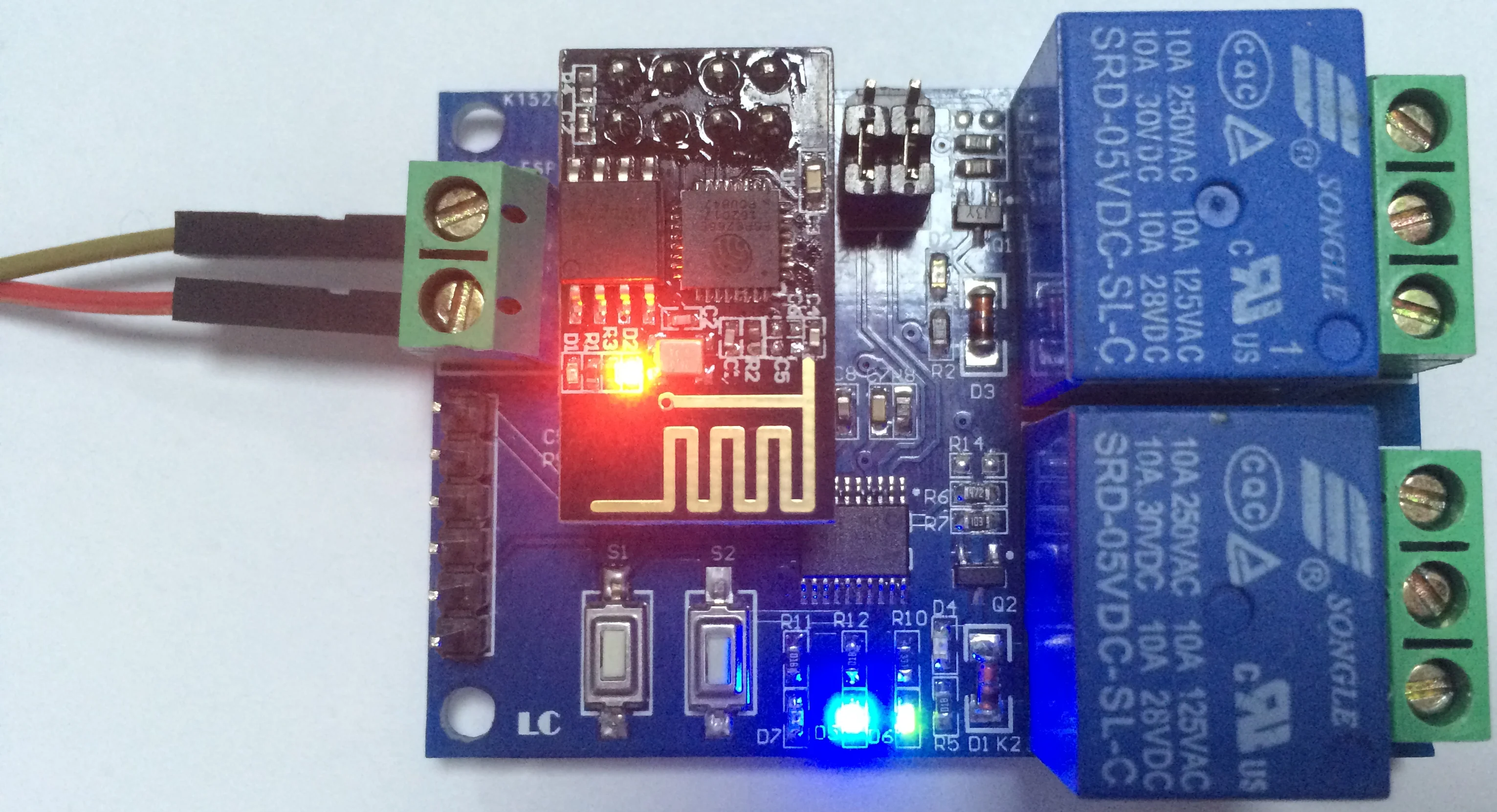
LED D5 (blue light) : Mode 2 indicator light
LED D6 (green) : working status indicator, described as follows:
(1) When it goes out, it means that it is self-configuring or losing connection with the router;
(2) When 0.5s flash, it means waiting for the mobile APP to configure the WiFi account and password for the ESP-01 module;
(3)2S slow-flash represents the completion of configuration and waits for the establishment of TCP connection with the mobile phone;
(4) Constant light represents the successful establishment of TCP connection with the mobile phone.
2 reserved jumper caps: Please plug them into the end (i.e., RX connected to RX1, TX connected to TX1) during normal use. If you want to use USB to TTL serial module to debug ESP-01 module alone, please plug them into the top (otherwise there may be interference).
COM1: Common End;
NC1: Normally closed end, the relay is short connected with COM1 before sucking, and suspended after sucking;
NO1: Normal start, the relay is suspended before pulling, and it is short-connected with COM1 after pulling.
COM2: Common End;
NC2: Normally closed end, the relay is short connected with COM2 before pulling, and suspended after pulling;
NO2: Normal start, the relay is suspended before pulling, and it is short-connected with COM2 after pulling.
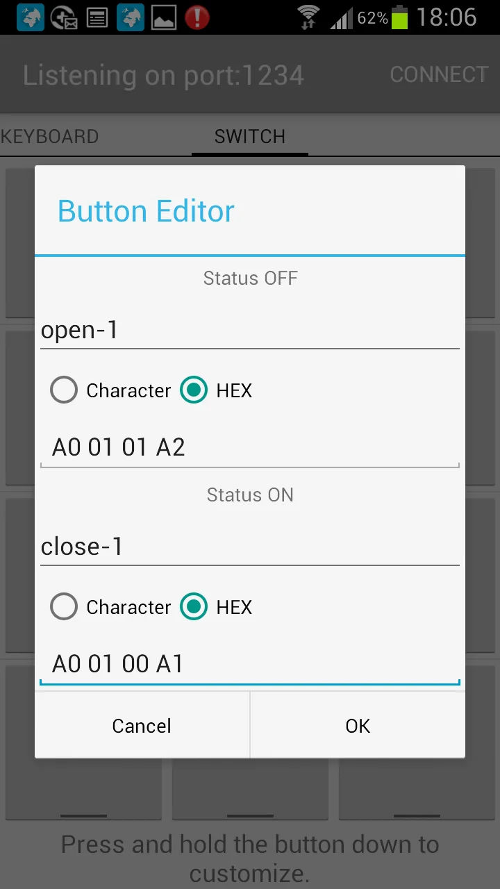
Relay control instruction (hex form) :
Open the first relay: A0 01 01 A2
Turn off the first relay: A0 01 00 A1
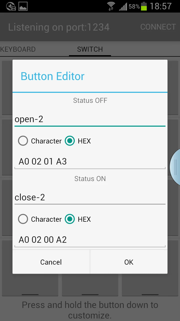
Turn on the second relay: A0 02 01 A3
Turn off the second relay: A0 02 00 A2
2. Prepare the following tools and software before use:
(1)12V/1A power adapter, the positive and negative poles of the power supply are respectively connected to the In + and In - modules;
(2) Install the APP "ESPTOUCH_DEMO" on the Android phone, which is used to configure the WIFI account and password for the ESP-01 module during the first use of working mode 2;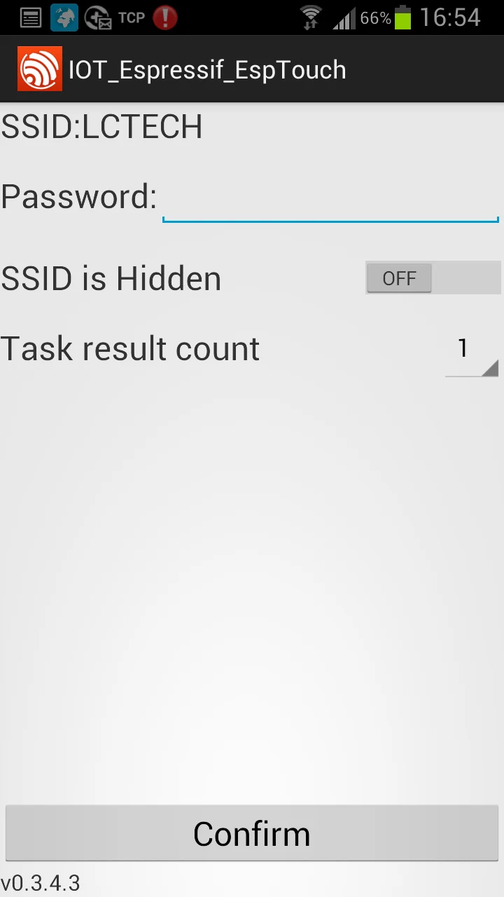
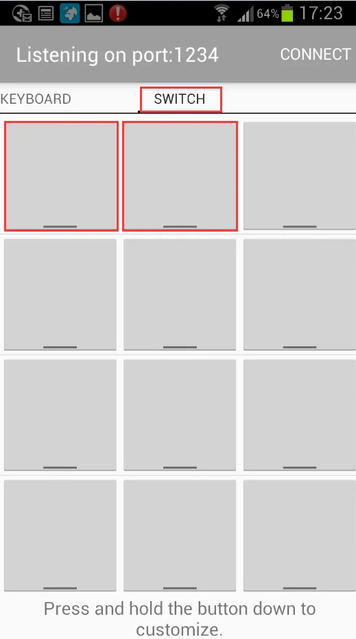
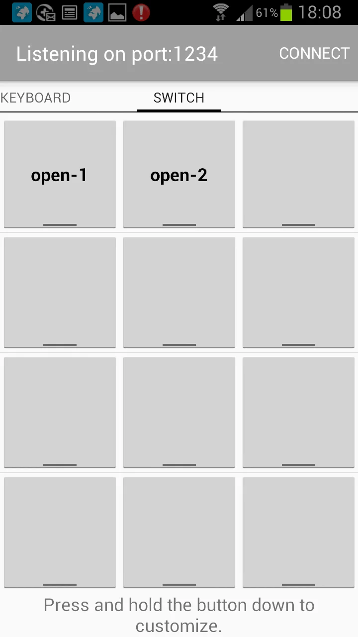
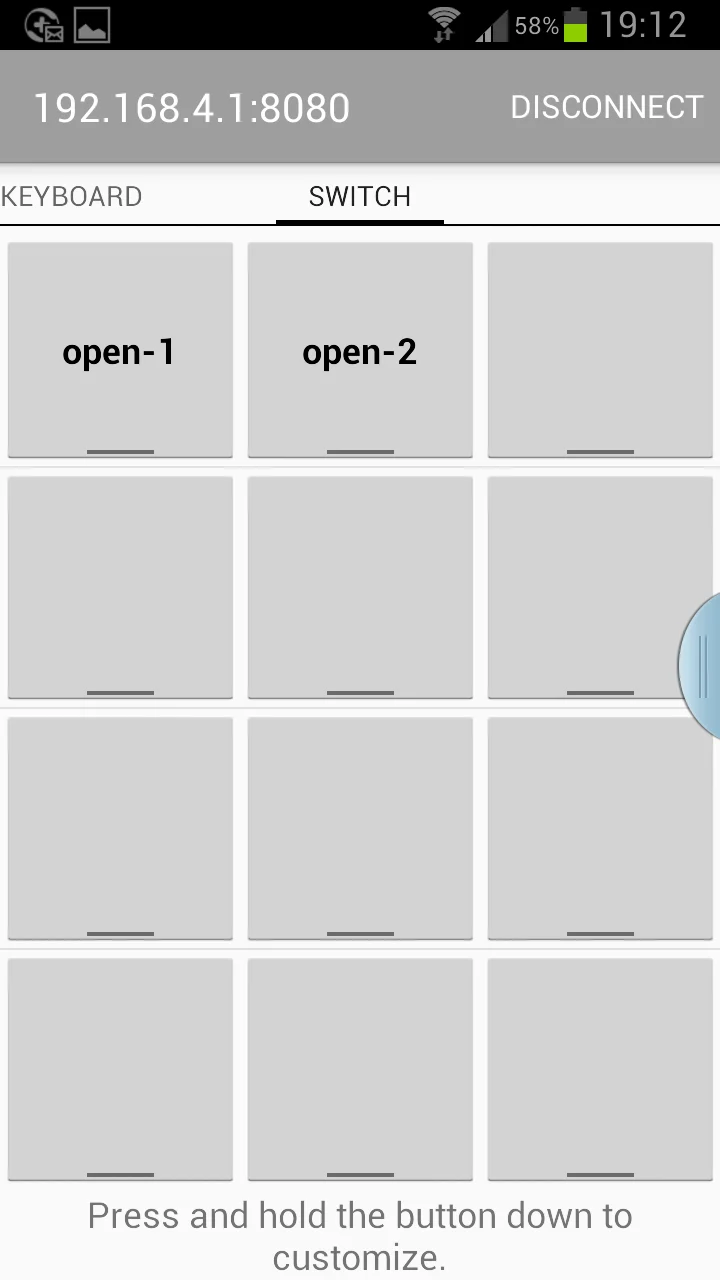
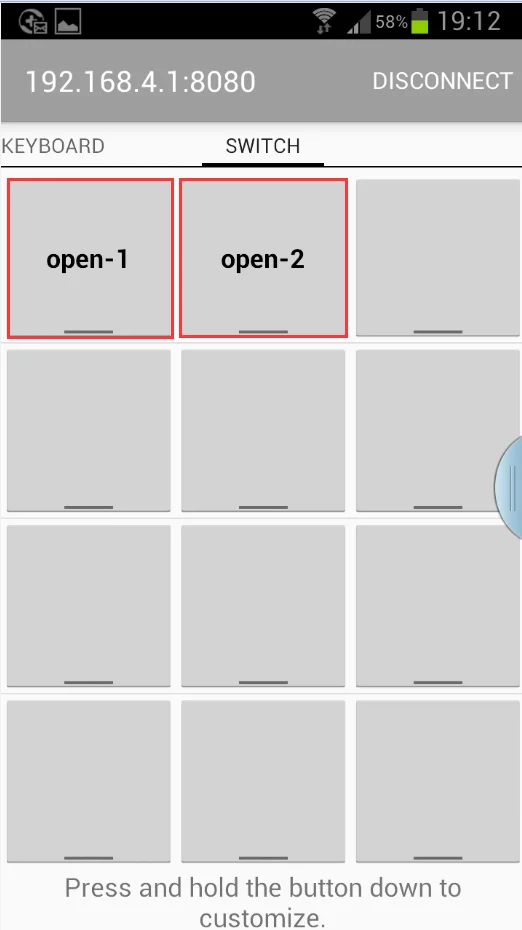
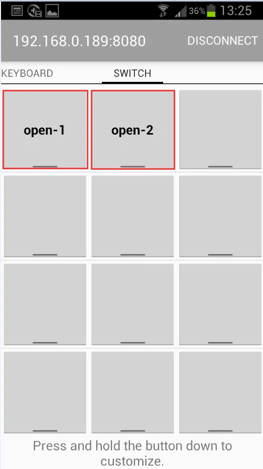
(3) Install APP "EasyTCP_20" on Android phone, TCP transmission tool, which is used to send relay control instructions. Click "Switch", and then long press the gray box in the interface to input the name and content of 2-way relay control instructions respectively (instruction format is in HEX form).
3. Operation mode 1 (the mobile phone is mounted on the ESP-01 module)
(1) Plg in the ESP-01 module and power on the module. After about 4S minutes, the green light changes from off to 2S slow flashing, indicating that the configuration is completed, as follows:

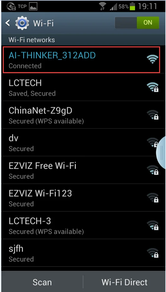
(2) Connect the mobile phone to the AP hot signal sent by the ESP-01 module
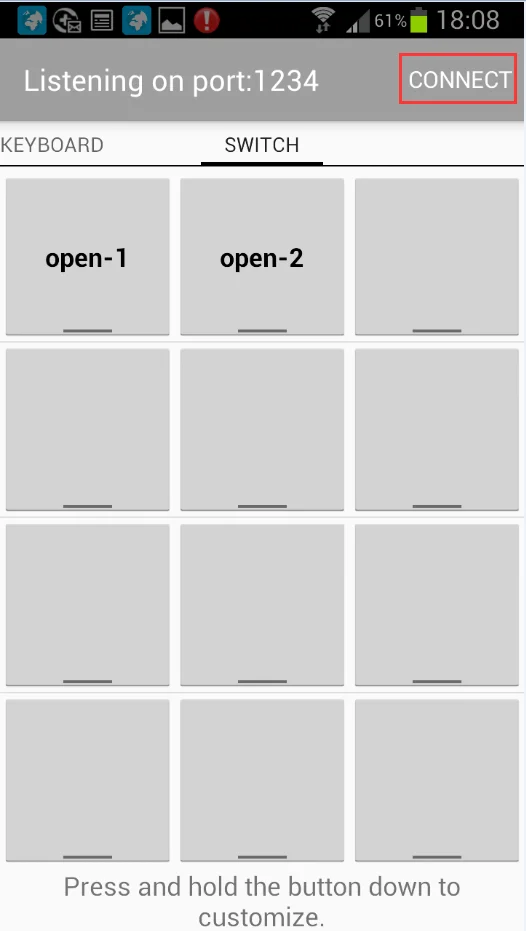
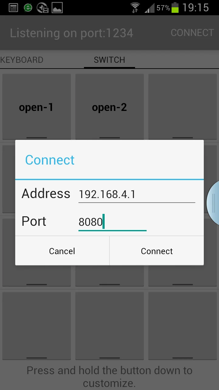
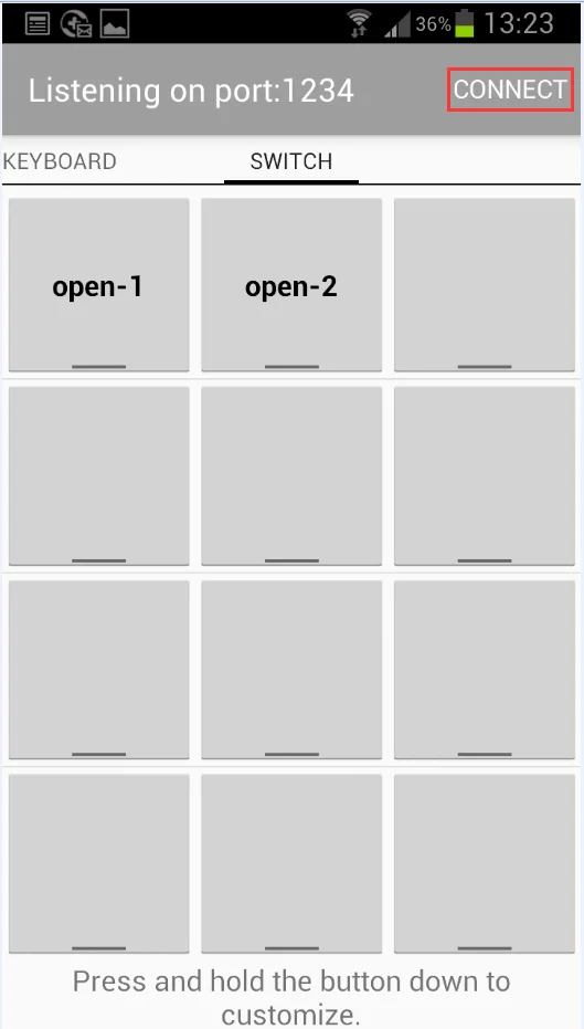
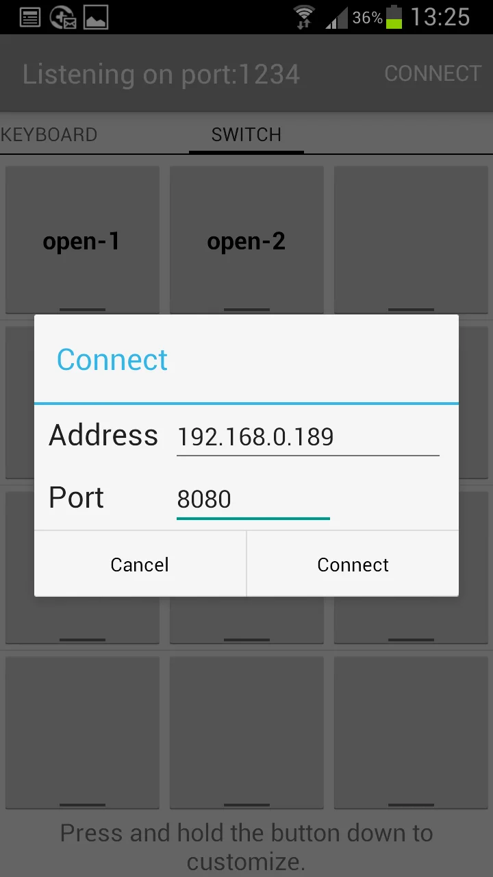
(3) Open the "EasyTCP_20" APP, click "Connect", enter IP address: 192.168.4.1 and port number 8080, then click "Connect", after the connection is successful, the green light will change from 2 seconds slow flash to normal light, click the gray box to send instructions to control the relay switch.
4. Operation mode 2 (mobile phone and ESP-01 module are mounted on the router at the same time)
(1) plug in the ESP-01 module, power on the module, wait for the green light to slow flashing, then press S1 key to switch to mode 2, the blue light will be on, and about 1 minute later the green light will change from off to 0.5s flash, indicating that you are waiting for the "ESPTOUCH_DEMO" APP to set the WiFi account and password for it
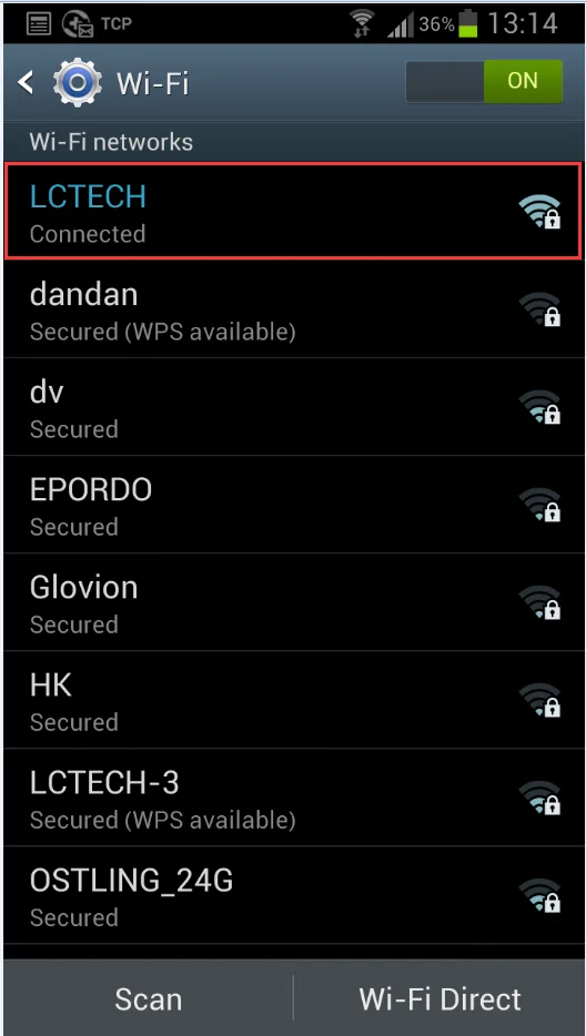
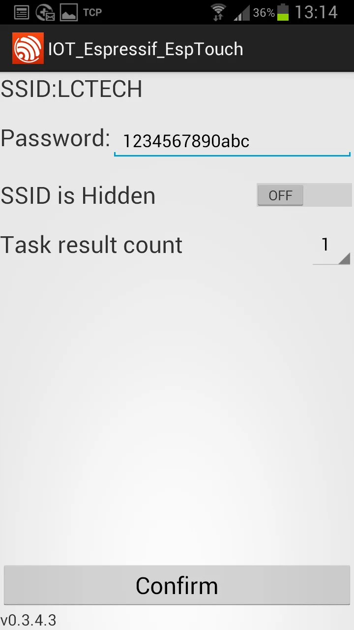
(2) At this time, connect the mobile phone to the router, open the "ESPTOUCH_DEMO" APP, enter the password of the router, and click "Confirm".
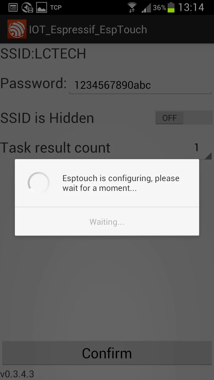
(3) Wait for the successful configuration. When the ESP-01 IP address (such as 192.168.0.189) appears on the APP interface, it means that the ESP-01 module has successfully connected to the router, and the account number and password will be automatically remembered. Next time you enter the mode 2, it will automatically connect (it can be connected about 20-60s).
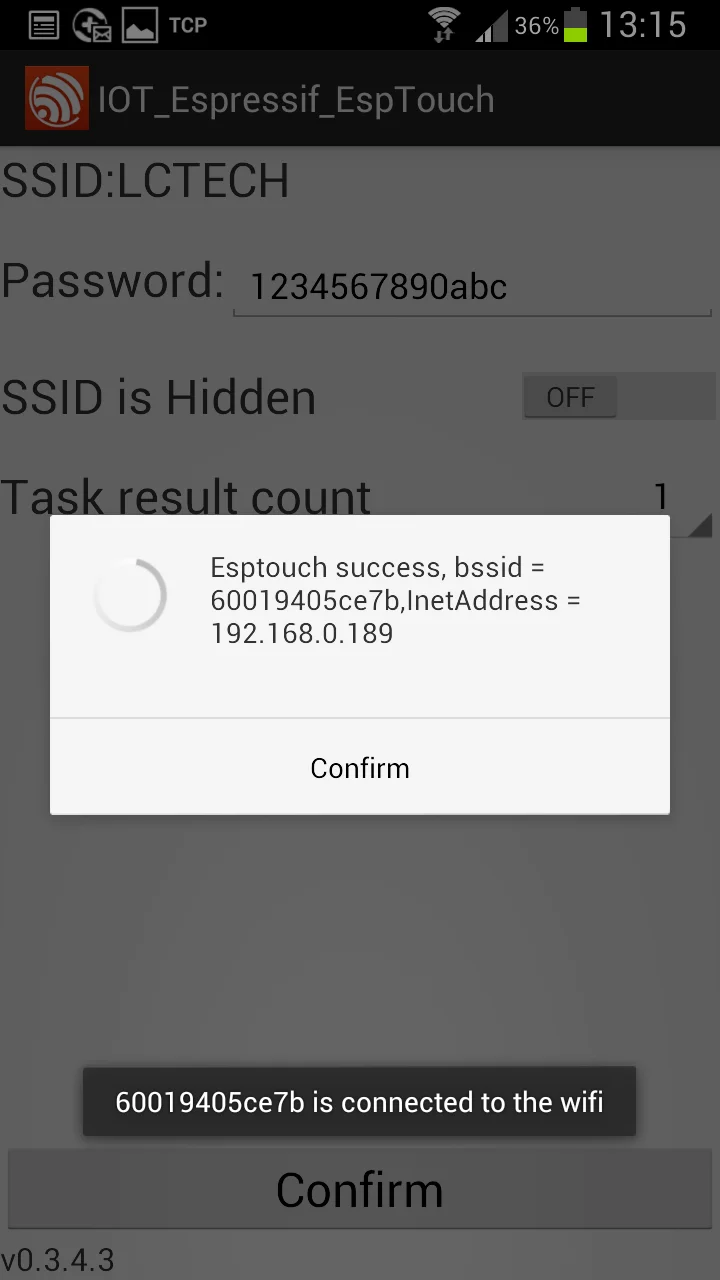
It is important to note that the IP address 192.168.0.189 is dynamically assigned to the ESP-01 module by the router. The address may change after the next reconnection. You can check the real-time IP address of the ESP-01 module in the router&x27;s device list.
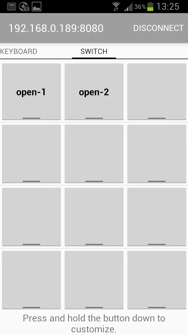
(4) Open the "EASYTCP_20" APP, click "Connect", and enter the IP address of ESP-01 module:192.168.0.189 and the port number 8080, and then click "Connect". After the connection is successful, the green light will turn from a slow flash for 2 seconds to a regular light. Click the gray box to send instructions to control the switch of the relay
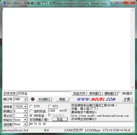
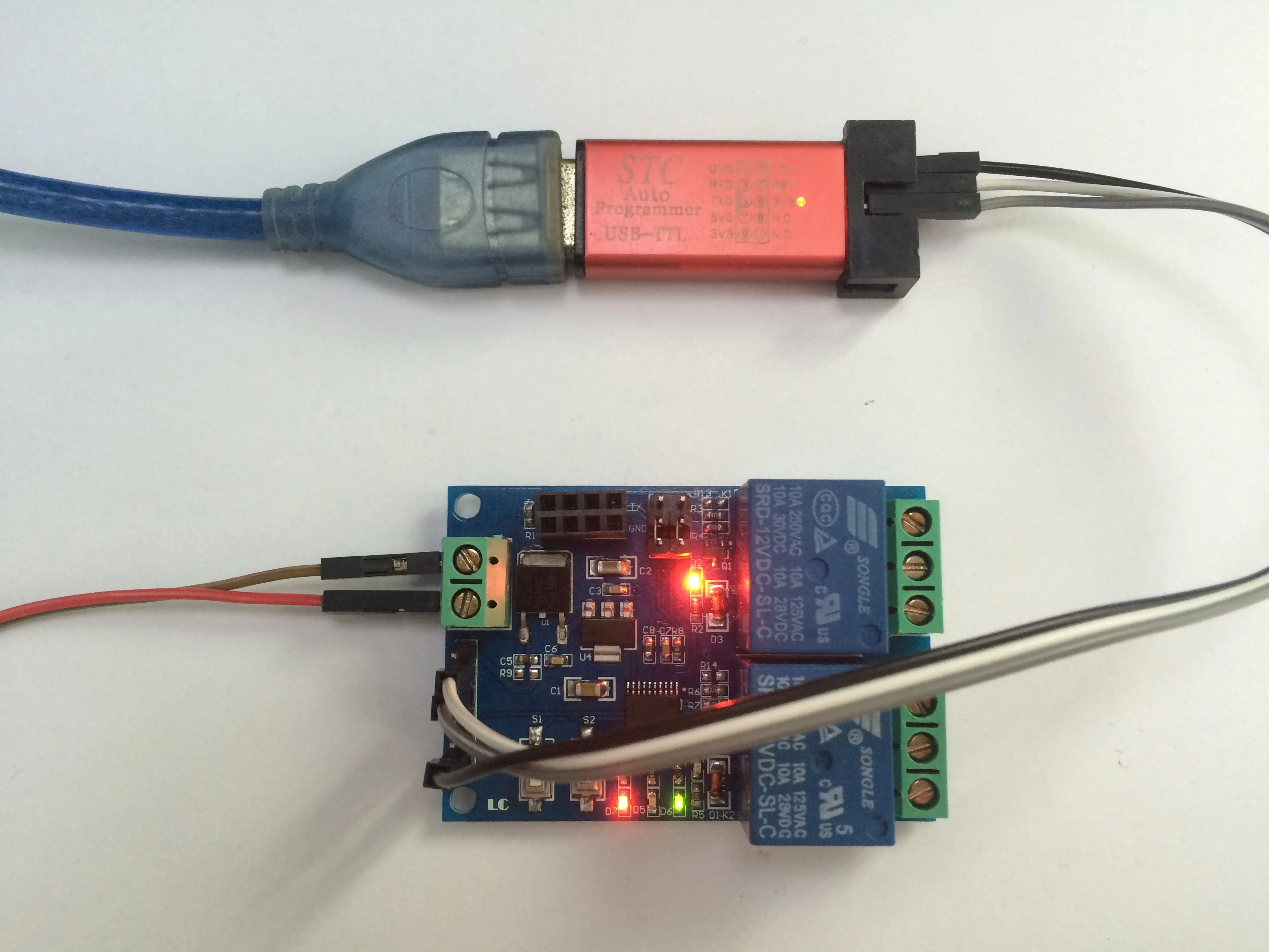
5. Additional function (as USB relay)
Prepare a USB to TTL serial port module, GND, TX and RX of TTL module are connected to GND, TX and RX of relay module respectively, unplug ESP-01 module, select mode 1, and open serial port debugging software (such as SSCOM32) on the computer after the green light turns to 2S slow flashing, and select bault rate as 115200.The first and second relay can be opened by sending A0 01 01 A2 and A0 02 01 A3 in hex form;Sent A0 01 00 A1 and A0 02 00 A2 in hexadecimal (HEX) form to close the first and second relay, respectively.Take opening the first relay as an example:
 Warm Tips:
1. It will take a little longer to configure the WiFi password for the first time (about more than 1 minute). After the completion of the configuration, it will only take 20 seconds to connect automatically after the next boot.
2. If you want to change the router, you can power off and restart it or press S2 (press S2 will erase the WIFI account and password you remembered before), and reconfigure the WIFI account and password for ESP-01 in mode 2.
3. When the router signal remembered by ESP-01 is weak or not in the service area, which leads to the connection interruption, the green light will be extinguished and the connection will be automatically attempted. During this process, the key is invalid.
4. In mode 1 and mode 2, the key can only be used when the green light is slow flashing or constant flashing for 2 seconds. The other cases are internal self-configuration of the chip or waiting for the configuration process, and the key is invalid.
5. ESP-01 has a timeout mechanism. When the phone contacts with ESP-01 without data for more than 6 minutes, the TCP connection will be automatically disconnected.
